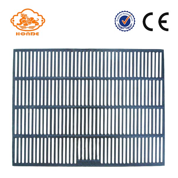
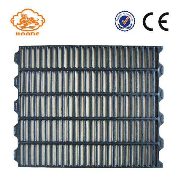
The structure of the filter press consists of three parts: Cast iron pig slats are made of high-quality cast iron and are characterized by their durability. Not only can be used for laying the floor of pig farms, but also for sheep, cattle and other farm floor laying, but also has the effect of insulation. Its chemical composition ensures maximum strength and endurance, with vertical ribs in the same direction, so sows can get up easily. Perfect alignment of the holes between the ribs to avoid damaging the sow's nipple. Easy to clean, quick to install.
595mm
Cast Iron Pig Slat,Pig Floors Cast Iron Slats,Cast Iron Slat For Pigs,Cast Iron Floor,Cast Iron Pig Flooring HuangHua FengYi Honde Metal Factory , https://www.farrowingcratesfromchina.com
1. The frame of the frame is the basic component of the filter press . The two ends are the thrust plate and the pressing head. The two sides of the frame are connected together. The beam is used to support the filter plate, the filter frame and the pressing plate. To meet advanced hygiene needs, the rack needs to be covered with stainless steel. Hangzhou Geente's stainless steel technology can be used as a reference, and its quality can meet the needs of European customers.
A. Thrust plate: It is connected with the support to place one end of the filter press on the foundation. The thrust plate of the box filter press is the feed hole in the middle, and there are four holes in the four corners. The hole is the inlet of the washing liquid or the press gas, and the lower two corners are the outlet (underflow structure or filtrate outlet)
b. Pressing plate: used to press the filter plate filter frame, and the rollers on both sides are used to support the pressing plate to roll on the track of the beam.
C. Girders: It is a load-bearing component. It can be coated with hard PVC, polypropylene, stainless steel or new anti-corrosion coating according to the requirements of environmental protection.
2. The pressing mechanism is manually pressed, mechanically pressed, and hydraulically pressed.
A. Manual compression: The compression plate is pressed by a screw type mechanical jack to press the filter plate.
B. Mechanical compression: The pressing mechanism consists of an electric motor (with advanced overload protector) reducer, gear, screw and fixing nut. When compacting, the motor rotates forward, driving the reducer and the gear to make the screw rotate in the fixed nut, pushing the pressing plate to press the filter plate and the filter frame. When the pressing force is getting larger and larger, the load current of the motor increases. When the current value set by the protector is reached, the large pressing force is reached, the motor cuts off the power supply and stops rotating, because the screw and the fixed wire have Reliable self-locking helix angle can reliably guarantee the compression state during the working process. When retracting, the motor reverses. When the pressure block on the plate is pressed, it will return to stop when it touches the stroke switch.
C. Hydraulic compression: The composition of the hydraulic compression mechanism consists of the hydraulic station, the cylinder, the piston, the piston rod and the hydraulic shaft of the Havran card hydraulic pump connected to the compression plate: motor, oil pump, relief valve ( Adjust the pressure) reversing valve, pressure gauge, oil circuit, fuel tank. When the hydraulic pressing machinery is pressed, the hydraulic station supplies high-pressure oil, and the component chamber formed by the cylinder and the piston is filled with oil. When the pressure is greater than the frictional resistance of the pressing plate, the pressing plate slowly presses the filter plate, when the pressure is pressed. When the tightening force reaches the pressure value set by the relief valve (displayed by the pressure gauge pointer), the filter plate, the filter frame (plate frame type) or the filter plate (box type) is pressed, and the relief valve begins to unload. When the motor power is cut off, the pressing action is completed. When retracting, the reversing valve is reversing, and the pressure oil enters the rod cavity of the cylinder. When the oil pressure can overcome the frictional resistance of the pressing plate, the pressing plate begins to retreat. When the hydraulic pressure is automatic pressure holding, the pressing force is controlled by the electric contact pressure gauge, and the upper limit pointer and the lower limit pointer of the pressure gauge are set to the values ​​required by the process. When the pressing force reaches the upper limit of the pressure gauge, the power supply When the oil pump stops, the oil pump stops supplying power. The pressure is reduced due to the internal leakage and external leakage that may occur in the oil circuit system. When the pressure is lowered to the lower limit of the pressure gauge, the power is turned on, the oil pump starts to supply oil, and when the pressure reaches the upper limit, the power is cut off. The oil pump stops supplying oil, and this cycle is used to achieve the effect of ensuring the pressing force during the process of filtering the material.
3, the filter mechanism <br> <br> filter constituted by the filter plate, filter box, cloth, squeezing the separator composition, on both sides of the filtration plate covered with a cloth, squeezing the separator takes the configuration, a set of diaphragm filter plates And side panels. The diaphragm plate is covered with a rubber diaphragm on both sides of the substrate, and the filter cloth is covered on the outer side of the diaphragm, and the side plate is an ordinary filter plate. The material enters each filter chamber from the time hole of the thrust plate, and the solid particles are trapped in the filter chamber due to the pore diameter larger than the filter medium (filter cloth), and the filtrate flows out from the liquid outlet hole below the filter plate. When the filter cake needs to be dried, in addition to pressing with a diaphragm, compressed air or steam may be used to pass through the washing port, and the air stream flushes the water in the filter cake to reduce the moisture content of the filter cake.
(1) Filtration mode The manner in which the filtrate flows out is clear flow filtration and dark flow filtration.
A. Bright flow filtration: a water nozzle is arranged on the lower liquid outlet of each filter plate, and the filtrate flows out intuitively from the water nozzle.
B. Underflow filtration: There is a liquid outlet hole below each filter plate, and the liquid outlet holes of several filter plates are connected into one liquid outlet passage, which is discharged by a pipe connected by a liquid outlet hole below the thrust plate.
(2) Washing method When the filter cake needs to be washed, it sometimes flows in one-way washing and two-way washing, undercurrent one-way washing and two-way washing.
A. The clear flow one-way washing is that the washing liquid enters sequentially from the washing liquid inlet hole of the thrust plate, passes through the filter cloth and then passes through the filter cake, and flows out from the non-porous filter plate, at which time the liquid discharging nozzle of the orifice plate is closed. In the state, the outlet nozzle of the non-porous plate is open.
B. The clear flow two-way washing is that the washing liquid is washed twice from the washing liquid inlet holes on both sides of the thrust plate, that is, the washing liquid is washed from one side and then from the other side, and the outlet of the washing liquid is the same as the inlet. The direction of the corner, so it is called two-way cross washing.
C. The dark flow unidirectional flow is that the washing liquid enters the perforated plate from the washing liquid inlet hole of the thrust plate, passes through the filter cloth and then passes through the filter cake, and flows out from the non-porous filter plate.
D. The undercurrent two-way washing is that the washing liquid is washed twice from the two washing liquid inlet holes on both sides above the stopper plate, that is, the washing is first washed from one side and then washed from the other side, and the outlet of the washing liquid is diagonal. Direction, so it is also called undercurrent two-way cross washing.
(3) Filter cloth: filter cloth is a kind of main filter medium. The selection and use of filter cloth plays a decisive role in the filtration effect. When selecting, it should be selected according to the pH value of the filter material, solid particle size and other factors. Material and pore size to ensure low filtration cost and high filtration efficiency. When using, ensure that the filter cloth is not flat and the hole diameter is smooth.
The cast iron slats we produce are very good for sows and piglets. We can produce a variety of cast iron sats, can also be based on customer requirements or customer drawings provided for production.


1286
600*600mm
14kgs
595mm
1287
500*600mm
14.5kgs
1289
600*600mm
18kg
595mm