CCD imaging principle and classification
one. How CCD works
Compared with traditional negatives, CCD is closer to the way the human eye works for vision. However, the retina of the human eye is composed of rod cells responsible for light intensity sensing and cone-shaped cells of color induction, and the division of labor forms a visual sense. After 35 years of development, the CCD has been shaped and shaped. The composition of the CCD is mainly composed of a mosaic-like grid, a concentrating lens, and a matrix of electronic circuits under the bottom. The companies that currently have the ability to produce CCDs are: SONY, Philps, Kodak, Matsushita, Fuji, SANYO and Sharp, most of which are Japanese manufacturers.
two. Three-layer structure of CCD
Decomposing the CCD structure reveals that in order to help the CCD to combine color images, the grid is developed into a regularly arranged color matrix composed of red R, green G and blue B filter lenses (three primary color CCD). There is a complementary color CCD (for CMYG.. Y yellow). Each CCD component consists of millions of MOS capacitors (depending on the CCD's pixels). When the shutter of the digital camera is turned on, the light from the image passes through the mosaic patches, which causes the photosensitive cathode's cerium oxide material to emit electrons (negative electricity) and holes (positive electricity). By externally adding voltage, these electrons and holes are transferred to another layer of different polarity for temporary storage. The amount of electrons is proportional to the amount of light received by the spot during the exposure process. In the brightest part of an image, more than 100,000 electrons may be accumulated.
Taking the common IL type CCD on the market as an example, all the generated charges after the exposure are transferred to the adjacent shift register, and are successively converted into signal streams to be read out of the matrix. These signals of different strengths will be sent to a DSP, which is a digital image processing unit. There is an A/D analog digital signal converter in this unit. This converter converts the continuous range of signals into a 2D planar representation series, which allows each pixel to have a tonal value. Apply this method and then form a grid of points. A point (pixel) now has binary data to indicate the amount of light it accepts, which can show the strength and weakness, and finally integrate the image output.
three. Four types of CCD
In response to different types of work requirements, the industry has developed four different types of CCDs: Linear Linear, Interline Scan, Panoramic Full-Frame and Frame-Transfer.
The Linear Linear CCD is composed of one-dimensional photosensitive dots. The image is scanned by the stepper motor. Since the photos are composed of lines and lines, the speed is slower than that of a digital camera using a 2-dimensional CCD. This type of CCD is mostly used on flatbed scanners.
The exposure step of the Interline Scanning CCD (STEP 1. - see figure) is the same as described above, except for the way the charge is read. The Interline CCD reads the signal from the scratchpad matrix through the vertical conveyor (STEP 2.) and then down to the bottom horizontal conversion recorder (STEP 3.), then the charge is moved to the amplifier (orange circle), after The horizontal photoelectric position and sequence are read out into the DSP, and finally an electronic signal is generated to represent a complete digital image. After clearing the scratchpad, reset the photo position to receive the next image. The advantage of the IL-type CCD is that it can store the charge in the scratchpad after exposure, and the component can continue to take the next photo, so the speed is faster, and the current reaction speed has reached more than 15 per second. However, the disadvantage of IL is that the temporary storage area occupies the area of ​​the photosensitive spot, so the dynamic range (Dynamic Range - the extent to which the difference between the brightest and darkest of the system can be expressed) is small. However, due to its high speed and low cost, more than 86% of digital cameras on the market use IL-type CCDs as the light-sensing components.
The Full-Frame CCD is a simpler sensitized design. In view of the shortcomings of IL, the FF improvement can utilize the entire photosensitive area (without the design of the temporary storage area), effectively increasing the light-sensing range, and also suitable for long-time exposure. The exposure process is the same as Interline, but the sensitization and charge output processes are separate. Therefore, a digital camera using an FF CCD must completely close the shutter when transmitting charge information to isolate the incident light from the lens and prevent interference. This also means that the FF must use a mechanical shutter (the electronic CLOCK shutter of IL cannot be used), and it also limits the continuous shooting capability of the FF CCD. Full-Frame CCDs are mostly used on the back of top-of-the-line digital cameras.
The frame-transfer CCD architecture is a product between IL and FF. It is divided into two parts. The upper part is the photosensitive area and the lower part is the temporary storage area. Overall, the Frame-Transfer CCD is very similar to the Full-Frame CCD, which features a large temporary storage area. Once the FT CCD is operational, it can quickly transfer the charge to the buffer area below, and itself can continue to take photos. This design allows the FT to use the same electronic shutter as the IL, but it also increases the light-sensing area and speed. The FT CCD was developed primarily by the Dutch company Philips, and the technology was later transferred to SANYO to develop VPMIX technology. Sanyo's improvement of VPMIX has been quite successful, enabling its digital camera to combine both static and animated shooting capabilities (up to 30 fps, excellent for animation).
four. Fuji SUPER CCD Cellular Technology
From the above article, we can understand that the CCD dot arrangement is the key to affecting the CCD's sensitivity range and dynamic capability. The early CCDs were all well-organized "plowing fields". When CCD technology arrived in Japan's Fuji, engineers began to think about CCD must be arranged like this? In order to have both the low-cost design of IL and the large sensation area of ​​FF, Fuji proposed a compromise CCD that broke the expert glasses. SuperCCD is the only CCD on the market that uses a honeycomb structure. It is based on the octagonal geometry and discontinuous arrangement, and is based on the IL method to maximize the effective area utilization of the CCD. However, the earlier technology made the channel too crowded and produced bad noise. Today, the SUPER CCD has developed into the third generation, and almost all the shortcomings have been improved.
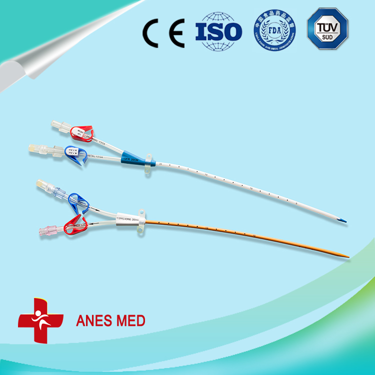
Hemodialysis Catheters are used to:
- Give long-term medicine treatment for pain, infection, or cancer, or to supply nutrition. A Hemodialysis Catheter can be left in place far longer than an intravenous catheter (IV), which gives medicines into a vein near the skin surface.
- Give medicines that affect the heart, especially if a quick response to the medicine is wanted.
- Give large amounts of blood or fluid quickly.
-
Take frequent blood samples without having to "stick" someone with a needle.
Receive kidney dialysis if you have kidney failure -
*Related Products:Anti-microbial Hemodialysis Catheter Kit,anti-microbial Hemodialysis Line Kit ,Anti-Microbial Dialysis Catheter kit.
.
-

Antimicrobia Hemodialysis Catheter
Antimicrobial Hemodialysis Catheter,Antimicrobial Hemodialysis Catheter Kit,Anti-Microbial Hemodialysis Catheter,Anti-Microbial Dialysis Catheter,Anti-microbial Hemodialysis Catheter Kit
Anesthesia Medical Co., Ltd. , http://www.sinoanesthesia.com